Octaviewer: Spherically parameterized progressive meshes
Introduction
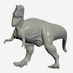
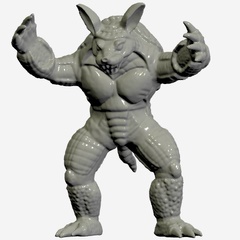
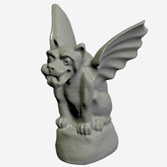
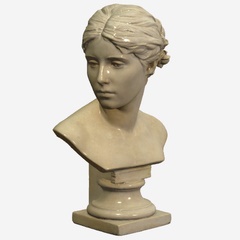
The goal is to enable the rendering of detailed 3D models (e.g., reconstructed scans) in a web browser using a compact representation, for applications such as digital archiving and computer-aided design.
Our approach converts traditional multi-chart texture atlases into spherically parameterized progressive meshes. This transformation addresses several key limitations of conventional texture atlases: seam artifacts at chart boundaries and difficulty in dynamically adapting mesh level-of-detail.

The key insight is to leverage spherical parameterization to avoid partitioning the surface into disjoint charts. Rather than working directly with the sphere, we use a related flat octahedron representation that unfolds naturally into a rectangular texture image.

This approach enables several important benefits: significantly reduced file sizes through better compression, seamless texturing with minimal discontinuities, and real-time level-of-detail adjustments in web browsers using a novel vertex parent indexing system.
Contributions
This project builds on several earlier techniques:
- Min-cycle topology simplification to pinch handles and tunnels [§6.2 in Collet et al. 2015]
- Spherical parameterization to remap onto a flat octahedron [Praun and Hoppe 2003]
- Stretch minimization to prevent undersampling at extremities [Sander et al. 2001]
- Appearance-preserving simplification to minimize visual errors [Cohen et al. 1998]
- Progressive meshes to create smooth level-of-detail geomorphs [Hoppe 1996]
- glTF compression (with Draco and AVIF) for a highly compact format [Rossignac 2002]
The main contribution is to demonstrate that all these concepts can come together, scale to large models, achieve impressive compression, and enable a fast Javascript viewer.
Scaling to models 300× larger than in [2003] involved major updates in the C++ mesh processing library, including multithreaded evaluation during mesh simplification and multithreaded optimization during spherical parameterization.
We demonstrate that mesh simplification and the creation of geometric morph sequences can be
achieved efficiently at runtime, even in Javascript,
by simply recording a parentIndex at each mesh vertex.
Implementation details
Higher-genus surfaces

Although the project originally targeted genus-zero meshes (i.e., deformed spheres), we are able to tackle higher-genus surfaces by “pinching” topological handles as a preprocess.
The idea is to iteratively find minimal nonseparating cycles (loops of edges that span a topological feature) and close the associated handle/tunnel. Each closed handle introduces two boundary loops within the parametric domain (see the white “holes” in this example).
Although these internal boundaries invalidate the guarantees of seamless texturing, the associated discontinuities are seldom noticeable.
Levels of detail sharing a read-only vertex buffer
A progressive mesh is formed by a sequence of edge collapse operations (see
this visualization).
In this project, we restrict the collapse of an edge {vs, vt} to result in one of
its endpoints, {vs}.
We enter vertices within the vertex buffer(s) in the order that they are introduced.
Crucially, this allows the vertex buffer to be shared and read-only:
any level-of-detail (LOD) mesh accesses a prefix of this shared buffer —
only its index array differs (due to the modified face connectivity).
We add a new vertex attribute parentIndex that records for each vertex (vs) the index of
the associated neighbor (vt) that spawned it
(or index zero if the vertex is present in the base mesh).
This parentIndex is sufficient to obtain any simplified mesh in two steps:
(1) traverse vertices fine-to-coarse, mapping vertex indices through the parent relations,
and (2) keep only non-degenerate triangles.
(See computeSimplifiedGeometry.)
Geomorphs
We can also use the parentIndex to construct a geometric morph from any mesh
to any coarser mesh in the progressive mesh sequence.
Again we traverse vertices fine-to-coarse, mapping vertex indices through the parent relations.
For each fine mesh vertex, we obtain its morph target attributes (position and uv)
as those of its ancestor vertex in the coarse mesh.
(See computeGeomorph.)
Morphing uv coordinates
Creating geometry with morphing uv coordinates is challenging in Three.js
because the uv attribute is not implemented within geometry.morphAttributes.
Currently, the awkward workaround is to manually add a morphTargetUv attribute and
patch the vertex shader using a material.onBeforeCompile callback.
Granularity of geomorph sequence
The number of geomorphs generated at runtime can be adjusted by addding the URL parameter
&config.morph.simplificationFactor=0.7.
For example, setting it to
0.92
leads to much finer granularity.
Other
config parameters
can be adjusted similarly.
Seamless texture reconstruction

Our textured mesh has fewer parametric discontinuities than a typical texture atlas
— the discontinuities consist of four edge paths that meet in a “+” shape,
as seen on the back of this model.
The boundary texels of the (uncompressed) texture are assigned to have reflection symmetry on each boundary, so that the bilinearly interpolated texture is continuous (C0) everywhere.
After lossy texture decompression, we should ideally update the texel values at the boundaries to reestablish continuity. Moreover, after aggressive compression, it may be useful to apply multiresolution feathering across several rows/columns of texels adjacent to the boundary for a gentler transition. This is costly in Javascript and fortunately it has not been found necessary.
Managing uv discontinuities across levels of detail
As is typical,
we represent the multiple uv attributes defined along the parametric discontinuity curves
by introducing duplicate vertices.
To avoid introducing surface cracks during mesh LOD changes,
(1) the progressive mesh is constructed to collapse these duplicate vertices in immediate succession,
and
(2) at runtime we atomically collapse successive vertices if they share the same current and parent 3D positions.
Anisotropic texture sampling

Enabling anisotropy=16 in the texture sampler is crucial.
Although a stretch-minimizing parameterization aims to reduce undersampling,
it often results in regions that are oversampled in certain directions.
With the default setting anisotropy=1,
even though the anisotropically oversampled texture is properly bandlimited,
the sampler conservatively avoids potential aliasing by accessing coarser mipmap levels, resulting in blurring.
Artifacts in the source atlas textures

Accurate sampling and filtering near atlas chart boundaries is challenging. When resampling the original atlas images onto our image domain, we often notice artifacts near the chart boundaries, as highlighted on the right. These artifacts are also visible when rendering the original source models, so repair would be difficult.
Resampling the original sensor data directly into the (continuous) spherical domain would further improve quality and compression.
Object-space normal maps

We represent fine surface detail using a normal map texture image. These normal maps are commonly defined in tangent-space, i.e., relative to normal and tangent vectors defined at mesh vertices and interpolated within triangles. However, these interpolated vector fields differ across geometric levels of detail, so do not form a consistent reference.
Instead, we use normal maps defined in object-space, i.e., relative to the coordinate system of the model.
Although this feature is supported in Three.js,
it is not currently in the glTF specification,
so we record this state in a (non-standard) userData field.
A side benefit of using object-space normals is that we no longer need to store normals and tangent vectors
at the mesh vertices.
Accounting for vertex reordering during mesh compression
Mesh compression schemes (including EdgeBreaker within Draco) usually reorder the vertices to realize
the best compression factor.
Because the progressive mesh does rely on an optimized ordering,
we store another vertex attribute originalIndex
that lets us permute the vertex data at load time to recover the expected ordering.
Results
Limitations
Parametric distortion
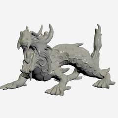
A spherical parameterization is most effective when the object is “sphere-like”. The collection of shapes in the demo pushes the boundaries in that respect, as it includes models with long limbs, horns, wings, and other extremities that result in unavoidable parametric distortion. This distortion in turn requires the use of anisotropic sampling, as discussed above, which may reduce rendering performance.Texture seams at topological handles

Recall that for meshes with nonzero genus, we pinch off the topological handles/tunnels, leaving general boundary curves within the parametric domain. The texture signal reconstructed by the graphics system along these curve loops is a piecewise bilinear function. Therefore, as is the case with ordinary texture atlases, the reconstructions cannot generally be made to match exactly (with C0 continuity) across the boundary. As shown inset, this results in seams in close-up views.
In future work, the perceptibility of these seams could be greatly attenuated by an optimization postprocess [e.g., Prada et al. 2018].
Future work
Promising framework for AI

A benefit of the flat-octahedral parameterization is that the surface signal is mapped continuously to a regular 2D grid structure. As showed in [Praun and Hoppe 2003], the mesh geometry itself can be resampled through the same map to produce a geometry image, where the (x, y, z) position coordinates are visualized here as R, G, B colors.
This type of multi-channel grid structure looks ideal for further analysis and processing using neural networks. However, one challenge is that 3D shape is not yet a pervasive digital medium like images, video, and text.
Software and resources
The processing is performed by several C++ programs, which are available here.
However, the scripts (involving Bash, Python, Perl, and Node.js) are in the process of being cleaned up.

